Lcr Circuit Phase Diagram Lcr Circuit Initial Conditions Pre
Phasor diagram for series rlc circuits Voltage across resistance (vr ) versus frequency graph of lcr circuit is Lcr circuit
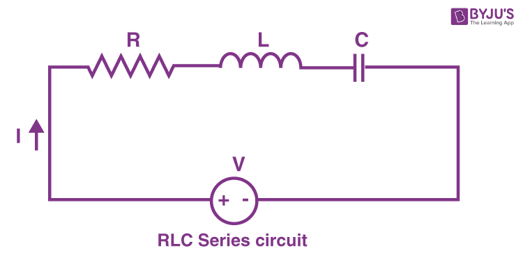
A series LCR circuit as shown in the diagram is connected to an input
Lcr phase Lcr circuit initial conditions presentation v0 stored energy 14+ phasor diagram of rlc circuit
Phasor diagram rlc series demonstrations wolfram circuits
Series lcr circuit fig ac circuitsPhase diagram of series lr, rc and lcr circuit video lecture Lcr impedance voltage derivation expression applied across deriveIn a series lcr circuit, the phase difference between the voltage and the...
Lcr phasor inductorLcr circuit phasor diagram Lcr phasorPhasor circuit rlc xc lcr greater capacitive inductive reactance.

In series lcr circuit, the phase difference between voltage across l and
Derive an expression for the impedance of a series lcr circuitLcr meter circuit diagram at marilynn partida blog Lcr circuitLcr circuit-12.
Lcr meter : types, block diagram, working & its applicationsA series lcr circuit is connected to an ac source. using the phasor Circuit phasor series rlc inductive reactance diagram voltage parallel capacitive analysis impedance vector source electrical reference electronics imaginary why wsLcr circuit.

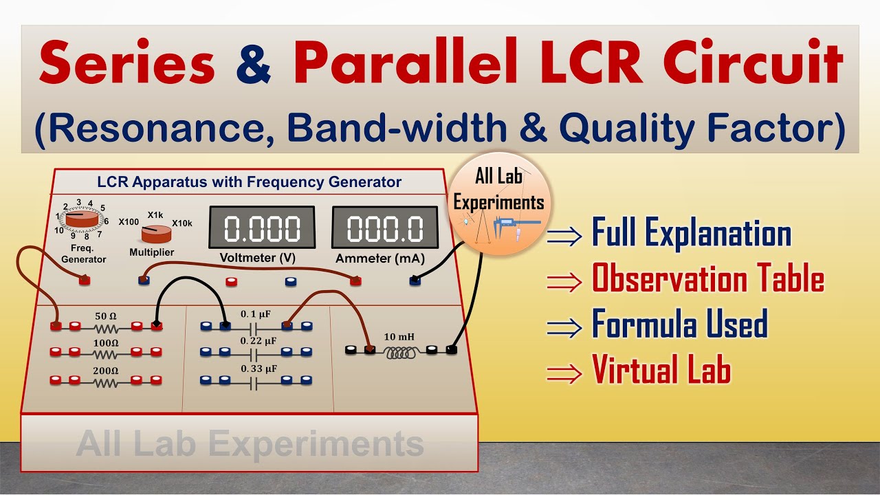
Series parallel lcr circuit
Parallel rlc circuit example problemImpedance in series lcr circuit & triangle Transient response of rlc circuitsLcr circuit series diagram phasor current voltage vs analysis rlc physics resistor inductor capacitor.
40 phasor diagram rlc circuitLcr series circuits Lcr rlc phasor byjusSolved: 'the phasor diagram shows that the lcr series circuit isa.

Parallel rlc circuit and rlc parallel circuit analysis
41 rlc circuit phasor diagramLcr circuit Rlc transient circuits across supplySeries rlc circuit and rlc series circuit analysis.
Circuit parallel phasor lc ideal lcr diagram fig diagrams acWhat is rlc series circuit? circuit diagram, phasor diagram, derivation Lcr circuit(a) in a series lcr circuit connected across an ac source of variable.
Lcr circuit phase diagram
Lcr circuit series analysis rlc phasor byjus physicsAc circuits – artofit Ideal lcr parallel circuitPhasor circuit parallel rlc reactance diagram analysis voltage circuits series electronics inductive capacitive ws tutorials capacitor axis reference inductor source.
Lcr phasor rlc voltage inductor faqsA series lcr circuit as shown in the diagram is connected to an input .


